Saturday, 9 July 2022

How virtual servers use routes

 How virtual servers using the routes.

The BIG-IP system contains two sets of routing tables:

  1. The Linux routing tables, for routing administrative traffic through the management interface
  2. A special TMM routing table, for routing application and administrative traffic through the TMM interfaces

 As a BIG-IP administrator, you can configure the system so that the BIG-IP system can use these routing tables to route both management and application traffic successfully.


Additional Information

When BIG-IP system using the routes it will select the most specific route to forward the traffic towards the destination.
About BIG-IP management routes and TMM routes:
 
Management routes
Management routes are routes that the BIG-IP system uses to forward traffic through the special management interface. The BIG-IP system stores management routes in the Linux (that is, kernel) routing table.
 
TMM routes
TMM routes are routes that the BIG-IP system uses to forward traffic through the Traffic Management Microkernel (TMM) interfaces instead of through the management interface. The BIG-IP system stores TMM routes in both the TMM and kernel routing tables.
 
 As described, the BIG-IP routing table consists of a combination of routing subtables. A subtable for management routes, and a  subtable for TMM routes. Routes in the TMM subtable are defined with a lower metric than routes in the management subtable. As a result, if an equally specific route exists as both a TMM route and a management route, the system will prefer the TMM route. This also applies if the only defined management route is a default gateway, the system will prefer the TMM default gateway.
 
TMM switch routes are routes that the BIG-IP system uses to forward traffic through the TMM switch interfaces instead of through the management interface. Traffic sourced from a TMM (self IP) address will always use the most specific matching TMM route. Traffic sourced from a TMM address will never use a management route. When TMM is not running, the TMM addresses are not available, and all TMM routes are removed. As a result, when TMM is not running, all outbound administrative traffic uses the most specific matching management route.
 
Starting in BIG-IP 11.3.0, you can configure source addresses from which virtual servers accept traffic. The BIG-IP system uses the destination address, source address, and service port configuration to determine the order of precedence applied to new inbound connections. When a connection matches multiple virtual servers, the BIG-IP system uses an algorithm that places virtual server precedence in the following order:

  • Destination address
  • Source address
  • Service port


Note:

NTP,SNMP,Syslog,Sflow ,remote authentication will always use the management default route unless a TMM interface has a layer2 connectivity to the IP's of those services,or you have a more specific route defined in TMM.


When BIG-IP system using the routes it will select the most specific route to forward the traffic towards the destination.
 
Example 1 - If the traffic is from the IP address 192.168.0.100 we have the below specific route defined.
 
net route /Common/192.168.0.100 {
    description none
    gw 192.168.0.2
    mtu 0
    network 192.168.0.100/32
    partition Common
}

 
So the traffic will be use the gateway IP 192.168.0.2 to direct the traffic.
 
 
Example 2 - If the traffic is from the one of the IP addresses in the network 192.168.0.0. For example let's take IP 192.168.0.102. In this situation the route below will be used.
 
net route /Common/192.168.0.0 {
    description none
    gw 192.168.0.1
    mtu 0
    network 192.168.0.0/16
    partition Common
}

 
So the traffic will be use the gateway IP 192.168.0.1 to direct the traffic.


Example 3 - If the traffic does not match any of the specific routes (neither 192.168.0.100 nor 192.168.0.0) above the BIG-IP system will forward the traffic to the default gateways like the ones you configured below.

default via 172.16.0.1 dev mgmt  metric 4096  <-------management route
default via 10.0.0.1 dev TEST-NET-1                      <-------TMM route

 
The traffic will be directed to the TMM route as it has the lower metric compared to the management route.


Commands:-

1.To check routing Table;tmsh show/net route

2.To check the configured static route:tmsh list/net route

3.To check the management route:list/sys management-route

4.To check the management interface IP address:list/sys management-ip.
What is a route domain?

 A route domain is a configuration object that isolates network traffic for a particular application on the network.

Because route domains segment network traffic, you can assign the same IP address or subnet to multiple nodes on a network, provided that each instance of the IP address resides in a separate routing domain.

Note: Route domains are compatible with both IPv4 and IPv6 address formats.
Important: For systems that include both BIG-IP Local Traffic Manager (LTM) and BIG-IP Global Traffic Manager (GTM), you can configure route domains on internal interfaces only.

Benefits of route domains

Using the route domains feature of the BIG-IP system, you can provide hosting service for multiple customers by isolating each type of application traffic within a defined address space on the network.

With route domains, you can also use duplicate IP addresses on the network, provided that each of the duplicate addresses resides in a separate route domain and is isolated on the network through a separate VLAN. For example, if you are processing traffic for two different customers, you can create two separate route domains. The same node address (such as 10.0.10.1) can reside in each route domain, in the same pool or in different pools, and you can assign a different monitor to each of the two corresponding pool members.

Sample partitions with route domain objects

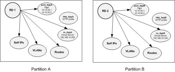
This illustration shows two route domain objects on a BIG-IP system, where each route domain corresponds to a separate customer, and thus resides in its own partition. Within each partition, the customer created the network objects and local traffic objects required for that customer's application (AppA or AppB).

sample partitions with route domains Sample partitions with route domains

Sample route domain deployment

A good example of the use of route domains is a configuration for an ISP that services multiple customers, where each customer deploys a different application. In this case, the BIG-IP system isolates traffic for two different applications into two separate route domains. The routes for each application's traffic cannot cross route domain boundaries because cross-routing restrictions are enabled on the BIG-IP system by default.
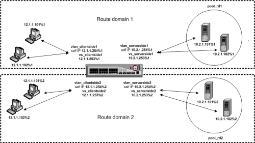
sample route domain deployment A sample route domain deployment

About route domain IDs

route domain ID is a unique numerical identifier for a route domain. You can assign objects with IP addresses (such as self IP addresses, virtual addresses, pool members, and gateway addresses) to a route domain by appending the %ID to the IP address.

The format required for specifying a route domain ID in an object’s IP address is A.B.C.D%ID, where ID is the ID of the relevant route domain. For example, both the local traffic node object 10.10.10.30%2 and the pool member 10.10.10.30%2:80 pertain to route domain 2.

The BIG-IP system includes a default route domain with an ID of 0. If you do not explicitly create any route domains, all routes on the system pertain to route domain 0.

Important: A route domain ID must be unique on the BIG-IP system; that is, no two route domains on the system can have the same ID.

Traffic forwarding across route domains

You can create a parent-child relationship between two route domains, and configure strict isolation, to control the extent to which the BIG-IP system can forward traffic from one route domain to another.

About parent IDs

When you create a route domain, you can specify the ID of another route domain as the parent route domain. The parent ID identifies another route domain that the system can search to find a route if the system cannot find the route within the child route domain.

For example, using the BIG-IP Configuration utility, suppose you create route domain 1 and assign it a parent ID of 0. For traffic pertaining to route domain 1, the system looks within route domain 1 for a route for the specified destination. If no route is found, the system searches the routes in route domain 0.

By default, if the system finds no route in the parent route domain, the system searches the parent route domain’s parent, and so on, until the system finds either a match or a route domain with no parent. In the latter case, the system refrains from searching any other route domains to find a match, thus preventing the system from using a route from another route domain.

Comparison of NATs and SNATs


Tuesday, 28 June 2022

What happens when you type a URL in browser

 This is quite interesting topic to discuss what exactly happens when you type an URL in the browser and press enter?


Let's see that step by step though this seems like a very tedious prolonged process when you will start reading the article we know that it takes less than seconds for a web page to render after we hit enter on our keyboard.

  1. You type maps.google.com into the address bar of your browser.

2. The browser checks the cache for a DNS record to find the corresponding IP address of maps.google.com.

DNS(Domain Name System) is a database that maintains the name of the website (URL) and the particular IP address it links to. Every single URL on the internet has a unique IP address assigned to it. The IP address belongs to the computer which hosts the server of the website we are requesting to access. For an example, www.google.com has an IP address of 209.85.227.104. So if you’d like you can reach www.google.com by typing http://209.85.227.104 on your browser. DNS is a list of URLs and their IP addresses just like how a phone book is a list of names and their corresponding phone numbers.

The main purpose of DNS is human-friendly navigation. You can easily access a website by typing the correct IP address for it on your browser but imagine having to remember different sets of numbers for all the websites we regularly access? Therefore, it is easier to remember the name of the website using an URL and let DNS do the work for us with mapping it to the correct IP.

In order to find the DNS record, the browser checks four caches.

● First, it checks the browser cache. The browser maintains a repository of DNS records for a fixed duration for websites you have previously visited. So, it is the first place to run a DNS query.

● Second, the browser checks the OS cache. If it is not found in the browser cache, the browser would make a system call (i.e. gethostname on Windows) to your underlying computer OS to fetch the record since the OS also maintains a cache of DNS records.

● Third, it checks the router cache. If it’s not found on your computer, the browser would communicate with the router that maintains its’ own cache of DNS records.

● Fourth, it checks the ISP cache. If all steps fail, the browser would move on to the ISP. Your ISP maintains its’ own DNS server which includes a cache of DNS records which the browser would check with the last hope of finding your requested URL.

You may wonder why there are so many caches maintained at so many levels. Although our information being cached somewhere doesn’t make us feel very comfortable when it comes to privacy, caches are important for regulating network traffic and improving data transfer times.It offloads the traffic on the main DNS server.

3. If the requested URL is not in the cache, ISP’s DNS server initiates a DNS query to find the IP address of the server that hosts maps.google.com.

As mentioned earlier, in order for my computer to connect with the server that hosts maps.google.com, I need the IP address of maps.google.com. The purpose of a DNS query is to search multiple DNS servers on the internet until it finds the correct IP address for the website. This type of search is called a recursive search since the search will continue repeatedly from DNS server to DNS server until it either finds the IP address we need or returns an error response saying it was unable to find it.

In this situation, we would call the ISP’s DNS server a DNS recursor whose responsibility is to find the proper IP address of the intended domain name by asking other DNS servers on the internet for an answer. The other DNS servers are called name servers since they perform a DNS search based on the domain architecture of the website domain name.

Without further confusing you, I’d like to use the following diagram to explain the domain architecture.

No alt text provided for this image


Many website URLs we encounter today contain a third-level domain, a second-level domain, and a top-level domain. Each of these levels contains their own name server which is queried during the DNS lookup process.

For maps.google.com, first, the DNS recursor will contact the root name server. The root name server will redirect it to .com domain name server. .com name server will redirect it to google.com name server. google.com name server will find the matching IP address for maps.google.com in its’ DNS records and return it to your DNS recursor which will send it back to your browser.

These requests are sent using small data packets which contain information such as the content of the request and the IP address it is destined for (IP address of the DNS recursor). These packets travel through multiple networking equipment between the client and the server before it reaches the correct DNS server. This equipment use routing tables to figure out which way is the fastest possible way for the packet to reach its’ destination. If these packets get lost you’ll get a request failed error. Otherwise, they will reach the correct DNS server, grab the correct IP address, and come back to your browser.

4. Browser initiates a TCP connection with the server.

Once the browser receives the correct IP address it will build a connection with the server that matches IP address to transfer information. Browsers use internet protocols to build such connections. There are a number of different internet protocols which can be used but TCP is the most common protocol used for any type of HTTP request.

In order to transfer data packets between your computer(client) and the server, it is important to have a TCP connection established. This connection is established using a process called the TCP/IP three-way handshake. This is a three step process where the client and the server exchange SYN(synchronize) and ACK(acknowledge) messages to establish a connection.

1. Client machine sends a SYN packet to the server over the internet asking if it is open for new connections.

2. If the server has open ports that can accept and initiate new connections, it’ll respond with an ACKnowledgment of the SYN packet using a SYN/ACK packet.

3. The client will receive the SYN/ACK packet from the server and will acknowledge it by sending an ACK packet.

Then a TCP connection is established for data transmission!

5. The browser sends an HTTP request to the web server.

Once the TCP connection is established, it is time to start transferring data! The browser will send a GET request asking for maps.google.com web page. If you’re entering credentials or submitting a form this could be a POST request. This request will also contain additional information such as browser identification (User-Agent header), types of requests that it will accept (Acceptheader), and connection headers asking it to keep the TCP connection alive for additional requests. It will also pass information taken from cookies the browser has in store for this domain.

Sample GET request (Headers are highlighted):

No alt text provided for this image

6. The server handles the request and sends back a response.

The server contains a web server (i.e Apache, IIS) which receives the request from the browser and passes it to a request handler to read and generate a response. The request handler is a program (written in ASP.NET, PHP, Ruby, etc.) that reads the request, its’ headers, and cookies to check what is being requested and also update the information on the server if needed. Then it will assemble a response in a particular format (JSON, XML, HTML).

7. The server sends out an HTTP response.

The server response contains the web page you requested as well as the status code, compression type (Content-Encoding), how to cache the page (Cache-Control), any cookies to set, privacy information, etc.

Example HTTP server response:

No alt text provided for this image


If you look at the above response the first line shows a status code. This is quite important as it tells us the status of the response. There are five types of statuses detailed using a numerical code.

● 1xx indicates an informational message only

● 2xx indicates success of some kind

● 3xx redirects the client to another URL

● 4xx indicates an error on the client’s part

● 5xx indicates an error on the server’s part

So, if you encountered an error you can take a look at the HTTP response to check what type of status code you have received.


8. The browser displays the HTML content (for HTML responses which is the most common).

The browser displays the HTML content in phases. First, it will render the bare bone HTML skeleton. Then it will check the HTML tags and sends out GET requests for additional elements on the web page, such as images, CSS stylesheets, JavaScript files etc. These static files are cached by the browser so it doesn’t have to fetch them again the next time you visit the page. At the end, you’ll see maps.google.com appearing on your browser.

All of these steps happens within milliseconds before we could even notice.

Traceroute Work and Example's of using traceroute command

 Traceroute is a network diagnostic tool used to track the route taken by a packet on an IP network from source to destination. It also calculates and displays the amount of time each hop took. Traceroute uses Internet Control Message Protocol (ICMP) echo packets with variable time to live (TTL) values in case of windows machine, it uses UDP packet in case of Linux.

Before executing the command traceroute, lets discuss few very important and basic facts.

Each IP packet that we send on the internet has got a field called as TTL. TTL stands for Time To Live. Although its called as Time To Live, its not actually the time in seconds, but its something else.TTL is not measured by the no of seconds but the no of hops. Its the maximum number of hops that a packet can travel through across the internet, before its discarded.

Hops are nothing but the computers, routers, or any devices that comes in between the source and the destination

What if there was no TTL at all?. If there was no TTL in an IP packet, the packet will flow endlessly from one router to another and on and on forever searching for the destination. TTL value is set by the sender inside the IP packet ( the person using the system, or sending the packet, is unaware of these things, but is automatically handled by the operating system ).If the destination is not found after traveling through too many routers in between ( hops ) and TTL value becomes 0 (which means no further travel) the receiving router will drop the packet and informs the original sender.

Original sender is informed that the TTl value exceeded and it cannot forward the packet further.

Let's say I need to reach 8.8.8.8 IP address, and my default TTL value is 30 hops (in case of windows) or 64 hops (in case of linux). Which means I can travel a maximum of 30 hops to reach my destination, before which the packet is dropped.But how will the routers in between determine the TTL value limit has reached. Each router that comes in between the source and destination will go on reducing the TTL value before sending to the next router. Which means if i have a default TTL value of 30, then my first router will reduce it to 29 and then send that to the next router across the path.The receiving router will make it 28 and send to the next and so on. If a router receives a packet with TTl of 1 (which means no more further traveling, and no forwarding ), the packet is discarded. But the router which discards the packet will inform the original sender that the TTL value has exceeded.

The information send by the router receiving a packet with TTL of 1 back to the original sender is called as "ICMP TTL exceeded messages". Of course in internet when we send something to a receiver, the receiver will come to know the address of the sender.Hence when an ICMP TTL exceeded message is sent by a router, the original sender will come to know the address of the router.

Traceroute makes use of this TTL exceeded messages to find out routers that come across your path to destination(Because these exceeded messages send by the router will contain its address).

But how does Traceroute uses TTL exceeded message to find out routers/hops in between?

You might be thinking, TTL exceeded messages are only send by the router that receives a packet with TTL of 1. That's correct, every router in between you and your receiver will not send TTL exceeded message. Then how will you find the address of all the routers/hops in between you and your destination. Because the main purpose of Traceroute is to identify the hops between you and your destination.

Lets take an example diagram of the whole process in the below diagram, where a sender does a traceroute towards one of the servers a remote location.

No alt text provided for this image


So let's say I want to do a traceroute to google's publicly available DNS server(8.8.8.8). My traceroute command and its result will look something like the below.

trace route 8.8.8.8

traceroute to 8.8.8.8 (8.8.8.8), 64 hops max, 52 byte packets

No alt text provided for this image

After looking at the output we might get so many questions like why the max hop is 64, why we are getting three different time for each hop, we will discuss all this point soon.

When I have executed that command of traceroute 8.8.8.8, what my computer does is to make a UDP packet (Yeah its UDP, because I am running this on linux machine ). This UDP packet will contain the following things.

  • My Source Address (Which is my IP address)
  • Destination address (Which is 8.8.8.8)
  • And A destination UDP port number which is invalid. Means the traceroute utility will send packet to a UDP port in the range of 33434 to 33534, Which is normally unused.

 So Let's see how this thing works.

 Step 1: My Source address will make a packet with destination ip address of 8.8.8.8 and a destination port number between 33434 to 33534. And the important thing it does it to make the TTL Value 1

Step 2: Of course my packet will reach my gateway server. On seeing receiving the packet my gateway server will reduce the TTL by 1 (All routers/hops in between does this job of reducing the TTL value by 1). Once the TTL is reduced by the value of 1 (1-1= 0), the TTL value becomes zero. Hence my gateway server will send me back a TTL Time exceeded message. Please remember that when my gateway server sends a TTL exceeded message back to me, it will send the first 28 byte header of the initial packet i send.

 Step 3:  On receiving this TTL Time exceeded message, my traceroute program will come to know the source address and other details about the first hop (Which is my gateway server.).

 Step 4: Now the traceroute program will again send the same UDP packet with the destination of 8.8.8.8, and a random UDP destination port between 33434 to 33534. But this time i will make the initial TTL 2.  This is because my gateway router will reduce it by 1 and then forwards that same packet which send to the next hop/router (the packet send by my gateway to its next hop will have a TTL value of 1).

Step 5: On receiving UDP packet, the next hop to my gateway server will once again reduce it to 1 which means now the TTL has once again become 0. Hence it will send me back a ICMP Time exceeded message with its source address, and also the first 28 byte header of the packet which i send.

 Step 6: On receiving that message of TTL Time Exceeded, my traceroute program will come to know about that hop/routers IP address and it will show that on my screen.

 Step 7: Now again my traceroute program will make a similar UDP packet with again a random udp port with the destination address of 8.8.8.8. But this time the ttl value is made to 3, so that the ttl will automatically become 0, when it reaches the third hop/router(Please remember that my gateway and the next hop to it, will reduce it by 1 ). So that it will reply me with a TTL Time exceeded message, and my traceroute program will come to know about that hop/routers IP address.

Step 8: On receiving that reply, the traceroute program will once again make a UDP packet with TTL value of 4 this time. If i gets a TTL Time exceeded for that also, then my traceroute program will send a UDP packet with TTL of 5 and so on.

 But how will my traceroute program come to know that the final destination of 8.8.8.8 has reached. The traceroute program will come to know about that because, when the original receiver of the packet 8.8.8.8 (remember that all UDP packet had a destination address of 8.8.8.8) gets the request it will send me a message that will be completely different from all the messages of "TTL Time exceeded".

When the original receiver (8.8.8.8) gets my UDP packet, it will send me a "ICMP Destination/PORT Unreachable" message. This is bound to happen because we are always sending a random UDP port between 33434 to 33534. Hence my Traceroute program will come to know that we have reached the final destination and will stop sending any further packets.

 Now lets take a Wireshark packet capture to understand this in practical.

No alt text provided for this image

From the above output we can see the UDP and the ICMP packet (since I am running the traceroute on my linux machine , I will describe this in more detail later in the post).

Notice the TTL value its first sets to 1 line. It starts from TTL of 1 and then 2, and then 3 so on. One important point to note here is that the trace route sends 3 UDP packet with the same ttl value in different sequence lets say if the first sequence is 1/256, then the second will be 2/256 and third will be 3/512 with the same ttl vale 1 , we can confirm the same from the below output.

No alt text provided for this image

But you might be wondering why my server is sending 3 UDP messages with TTL value of 1 and then 2 and then 3.?The reason behind this is to calculate an average Round Trip Time. Traceroute program sends three UDP packets to each hop to measure the exact average round trip time. Round trip time is nothing but the time it took to send and then receive the reply in milliseconds.  

So the bottom line is my traceroute program sends three UDP packets to each hop to simply calculate the round trip average. because the traceroute output shows you those three values in its output. Please see the traceroute output more closely. It shows three millisecond values for each hop. To get a clear idea about the round trip time.

traceroute to 8.8.8.8 (8.8.8.8), 64 hops max, 52 byte packets

1 10.200.200.200 (10.200.200.200) 256.162 ms  251.602 ms 253.542 ms

One more interesting thing to note is that each time my traceroute program is sending a different random UDP port number. This is to identify the reply belonged to which packet. As told before the reply messages send by the hops and destination contains the header of original packet we send, hence traceroute program can accurately calculate the round trip time (For each three UDP packets send to each hop), as it can easily identify the reply and correlate. The random port numbers are sort of identifiers to identify the reply.

The reply messages looks like the below.

No alt text provided for this image

iRule

  iRule: -- o iRule is a powerful and flexible feature within the BIG-IP local traffic management (LTM). o IRule is a powerful & flexibl...